
A couple of weeks back I started a project to develop a controller for my indoor hydroponics garden. This is the first in what will be a series of posts, bringing you assimilated knowledge from multiple sources while also helping me archive the development process.
Around October 2018, me and some of my college friends started an experiment in Hydroponics, we wanted to understand the basics and have a taste of how easy or difficult it was to grow a plant this way. Essentially, we wanted to dip our toes and test the waters with minimum time and effort. We started a single tomato(encrypted word) plant in a bucket using nutrients from Amazon and just left it out in the sun. It grew quite well for sometime but around December as the temperature plummeted, the plant began to wither, for a while we left it on its own but with further signs of impending doom, we decided to take it in and placed it indoors under a 100 Watt Incandescent bulb. The bulb was manually controlled at first but then we regularly failed to flick that switch on time, hence it was moved to an Arduino. In this upgrade, we also installed a Hair-dryer and a DHT11 temperature sensor for better temperature control. The plant flourished for a while but then stopped growing once again. The problem turned out to be in the nutrients, we had neglected checking the pH and salt concentrations. Anyway, we corrected it and had a reasonable harvest, but far from ideal.
The trial taught us a lot, but it also gave us conclusive proof of our laziness(wonder how engineers raise kids). Kids are something for the future but a garden was today’s problem. Hence this quick and simple project with the following requirements-
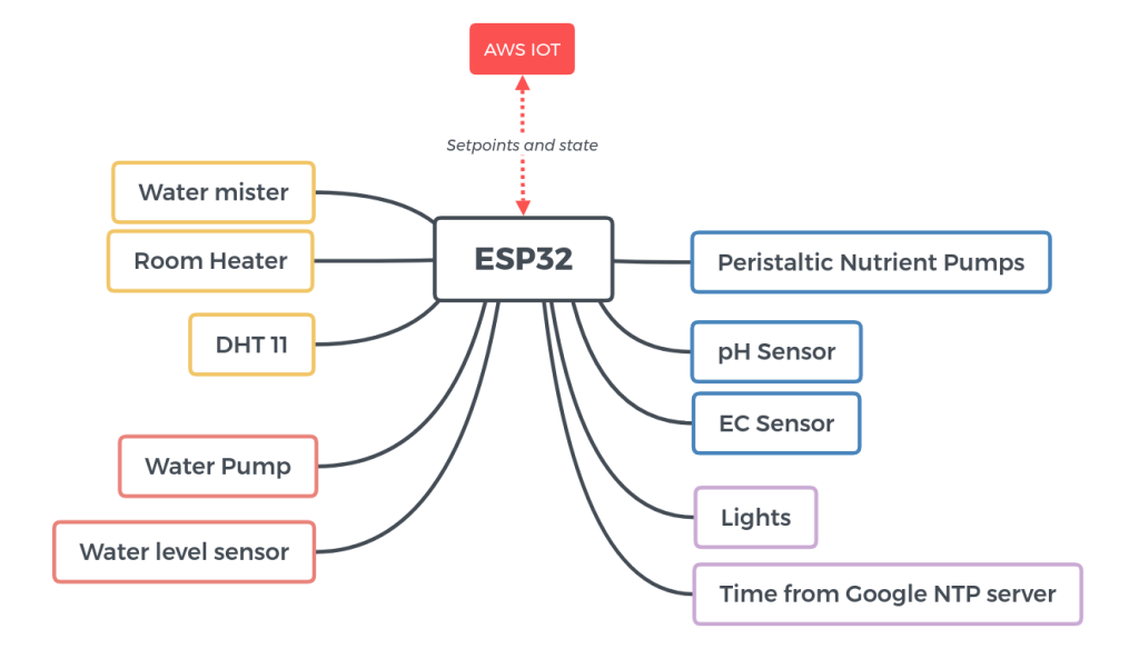
- Control following parameters for the grow room-
- Temperature (DHT11)
- Humidity (DHT11)
- Lights (LED tubelights)
- Nutrient solution concentration(analogue, diy ec probe)
- Nutrient solution pH(analogue pH sensor off Amazon)
- Logging of the above parameters for analytics(planned 😉)
- Allow adjustment of the set-points through a web application or an android application
- Keep local backup of the last received set-points
- Issue alerts if control for any of the parameters is failing
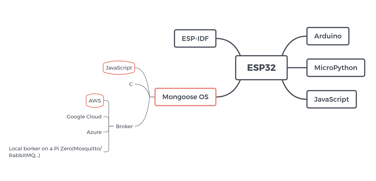
An initial search for “IOT development board” yielded two prominent results, NodeMCU and the ESP32 dev board. Not having followed the IOT maker space for the last two years, these two boards were unheard of to me, but on-board WiFi and Bluetooth with a 240 MHz dual core processor for ₹ 500 was quite interesting. A bit more googling on the community, support, development options and examples sorted out the ESP32 as my platform for this project.
The ESP32 is a recent Chinese offering and is the go to board for IOT makers these days for its low price and handsome hardware. The board has developed a sizeable community and you can find support with relative ease, should you stumble.
There are multiple options available for software development, but three of the most popular ones would be ESP-IDF, Arduino and Mongoose OS in no particular order. I decided to take Mongooose OS and code in JavaScript as I will not be running any resource intensive tasks, the control scheme is relatively simple for all of the parameters.Also, I do not have much of a background in Micro-controller programming and this way I could execute the development with relative ease.
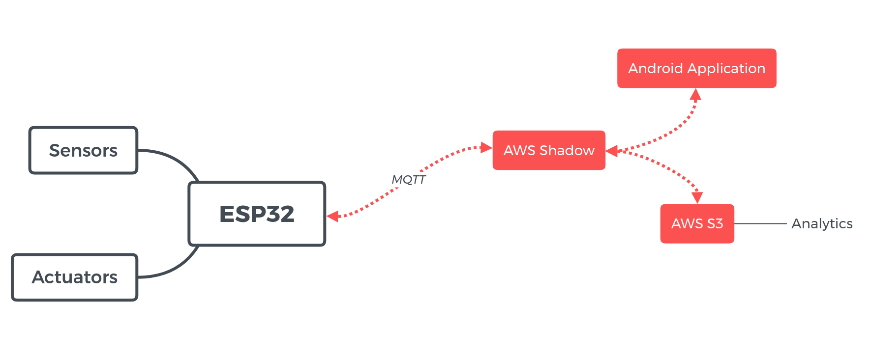
MQTT was chosen as the communication protocol for its ease of implementation, popularity(brings along community support) and robustness, in that order. The broker was chosen to be AWS because, first- its AWS, second- it is free for one year and third- didn’t have to buy a pi. Since, I was already using AWS, I also decided to use their Device Shadow implementation which basically creates a virtual device in the cloud that the UI can interact with even when the actual device is offline. The changes are communicated to the physical device when it come online.
How to get a Shadow service running with the ESP32 and AWS?
- Register on the AWS website
- Clone https://github.com/mongoose-os-apps/example-shadow-js and use the sample code for step 3, the code referred to on the below link uses an older AWS library.
- Follow the steps on this page https://mongoose-os.com/docs/mongoose-os/cloud/aws.md
- Use the files and folder structure from step 2 for further development
Non-Essentials and Quirks-
- Save device configuration parameters during Flash-
- run mos conf-get in the mos UI, this prints a list of configuration parameters on the current device
- add AWS certificate and key files to the fs folder if configuring the AWS MQTT connection in mos.yml
- find the configurations that you want to be set during flashing and add those to the mos.yml file, the example shown below is for WiFi configuration
config_schema:
 - ["wifi.sta.enable", true]
 - ["wifi.sta.ssid", "ssid"]
 - ["wifi.sta.pass", "password"]
- To set the time zone-
config_schema:
 - ["sys.tz_spec", "s", "IST-5:30", {title: "Time Zone: See formats for the TZ env var: \"man tzset\""}]
- What happens in case of Run-time errors?
- The OS supports a very small subset of JavaScript, many regular keywords like switch-case are undefined, it will throw an undefined keyword error in such cases
- Certain errors like using undefined variables will simply hold the script from executing without any print
- Errors in function calls also result in a similar looking situation
- Stack Overflow error-
- Due to the lack of a switch-case construct, I ended up using around 20 nested if-else statements in one case, and the OS printed a message – Guru Meditation Error-canary watch-point triggered
- This is a stack-overflow error and can be prevented by increasing the stack allocation, add the following lines to mos.myl, this is double the default stack size
cdefs:

  MGOS_TASK_STACK_SIZE_BYTES: 16384
Around 25% of the work has been done, I will be describing the project from a Hydroponics specific perspective when it is more complete, with the transducers, actuators and control strategy employed.
